

Knowledge
 Leak calculation in accordance with standards
Special-Knowledge
From experts for experts
Leakage calculation in accordance with EN 60534 and EN 12266
When it comes to control valve testing, experience shows that the level of knowledge how to properly calculate a leak limit is rather low. An explanation for the lack of knowledge could be found in the testing standard EN 60534-4 itself. It simply does not give a profound explanation on the calculation. It only lists a few examples where the leak limit is miraculously created out of few given Information. Those who follow the hint and take a look at the referenced EN 60534-2-1 will find themselves right in the middle of the control valve design calculation jungle. That is the moment when the tester understandably gives up and decided not to deal with it any more. That is why we did write this white paper. It is supposed bring light into the darkness of standards and to take away the horror of threatening mathematics.
Table of contents
- 01. Background
- 02. Basics of EN 60534-4
- 02.1 Location determination
- 02.2 What the standard “says ...
- 02.3 Facts and errors
- 03. Leakage calculation for c ...
- 03.1 Calculation in 3 steps
- 03.2 What is flow restriction?
- 03.3 Calculate air leakage in ...
- 03.4 Calculate water leakage i ...
- 03.5 Accuracy of results
- 04. Leakage calculation for c ...
- 04.1 Calculation for test flui ...
- 04.2 Calculation for test flui ...
- 05. Leakage calculation for c ...
- 06. ANSI FCI70-2 and EN 60534 ...
- 07. Appropriate measurement t ...
- 08. Leakage calculation in ac ...
Background
As a manufacturer of test benches, both for valve manufacturers and service companies, METRUS GmbH has been familiar with the normative requirements for test procedures for over 40 years. Leakage calculations never played a role until a few years ago. They were simply left to the operators. With the growing popularity of test bench software, however, the expectation grew that leakage could be calculated easily with the software. Today a standard-compliant leakage calculation is part of the software solutions we offer. Consequently, a comprehensive understanding of the interrelationships is mandatory.
Basics of EN 60534-4
Before turning to the actual calculation, it is very useful to understand the environment in which the “Test standard EN 60534-4” operates and what it says in simple terms about the permissible leakage.
Location determination
The higher-level framework is provided by the EN 60534 standard entitled “Industrial-process control valves”. It summarizes all relevant topics for control valves. Two parts of this standard are particularly important for the leakage calculation:
Part 4: 60534-4 Inspection and routine testing – only applies to testing and includes Table 3 in section 5.5.4 – Maximum permissible seat leakage for each leakage class. Leakage calculation is NOT possible with this part alone!
Part 2-1: 60534-2-1 Flow capacity. Sizing equations for fluid flow under installed conditions. This part is the source of the formulas listed in the example part of 60534-4.
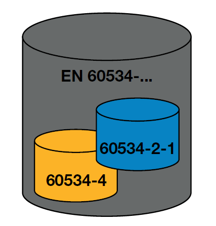
Image 1
These two parts of the standard are connected by the term “rated capacity” in table 3 of standard 60534-4.
What the standard “says” about permissible leakage
Understanding the calculations is much easier if the underlying context is literally put into words. In the case of leakage calculation of control valves, this can be formulated as follows:
1) Control valves regulate the flow rate which is controlled by the position of the actuator (plug, ball, butterfly valve, …).
2) If the actuator is in the nominal opening position (100% open), the resulting flow rate is called “rated capacity”.
3) Depending on the leakage class, a closed control valve may still have a very small flow rate as leakage.
4) For leakage classes I to IV-S1, the permissible leakage is calculated as a proportion of the rated capacity.
5) Leakage classes V and VI calculate the leakage directly from the seat diameter (not via the rated capacity).
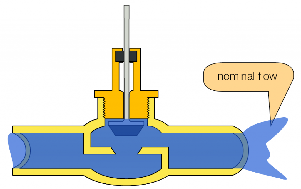
Image 2: Cone in rated travel position >> Rated capacity
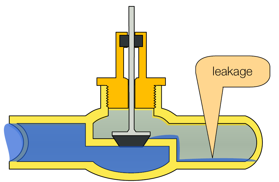
Figure 3: Closed valve with leakage
Facts and errors
The understanding of the calculation is made even easier by the following facts. They should also clear up widespread errors:
The Cv (or KvS) is NOT the “rated valve capacity” mentioned in 60534-4 Chapter 5.5.4 Table 3 “Maximum seat leakage for each leakage class”.
The Cv – rated flow coefficient – is a characteristic of the valve alike nominal pressure PN, nominal width DN or others. Definition: “The value specifies the amount of water (with a temperature between 5 and 40 °C) that flows through the valve at its nominal stroke (100%) and a pressure difference of 1 bar between inlet and outlet.” The unit of the Cv value is m³/h.
Based on Cv and EN 60534-2-1 a rated capacity for water AND for air are calculated.
A simple CONVERSION between water and air leakage does NOT exist.
Leakage calculation for classes I to IV-S1
Calculation in 3 steps
Regardless of the test fluid leakage calculation for classes I to IV-S1 is always done in three steps:
1) Check for flow restriction
2) Calculate the rated capacity Q [m³/h] according to EN 60534-2-1
3) Multiply the rated capacity Q with the leakage factor as per EN 60534-4
What is flow restriction?
The flow through a pipe or valve essentially depends on the pressure difference between inlet and outlet. The higher the pressure difference, the stronger the resulting flow. However, this correlation cannot be arbitrarily increased. An infinite pressure difference does not lead to an infinite flow.
In general, the flow velocity of a fluid is limited by the speed of sound (inside the fluid itself). For gas and air the flow velocity can consequently never exceed the speed of sound. Within liquids there is an additional physical effect – cavitation – in addition to the speed of sound limitation. The faster the liquid velocity, the lower the static pressure inside the liquid will be. If the static pressure falls below its specific vapour pressure, vapour bubbles appear – the liquid begins to foam. However, the speed of sound is considerably lower in foam than it is in the liquid. Meaning the flow velocity falls down to well below the liquid’s speed of sound. Cavitation slows down the flow velocity, restricting it to the speed of sound in foam.
As already mentioned, test standard EN 60534-4 calculates the permissible leakage as a proportion of the rated capacity. However, since this rated capacity cannot become arbitrarily high, it makes sense to check in the first step whether flow restriction is present.
For the “test for flow restriction”, two valve parameters are required which can be obtained from the manufacturer or taken from the tables in EN 60534-2-1:
- XT (also called Xchocked) – The Greek letter “Chi” refers to the “differential pressure ratio for gases at which flow restriction occurs”.
- FL – Pressure recovery factor for liquids
The following table contains examples of XT and FL values for selected valve types. An extended list can be found in EN 60434-2-1.
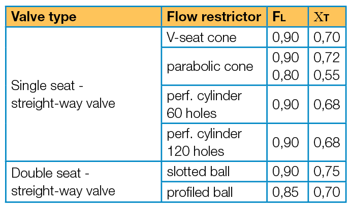
Table 1: Examples of XT and FL values
Calculate air leakage in 3 steps
To calculate the permitted leakage for a test with air the following steps shall be performed in sequence:
Step 1 – Check for flow restriction
Calculate: Differential pressure ratio X of the test situation.
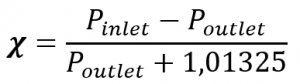
Pressures in [bar]
If the valve outlet is open to environment Poutlet = 0
Check: If the existing differential pressure ratio X of test is smaller than the critical differential pressure ratio XT, X is used for the calculation, otherwise use XT
In mathematical words: X < XT -> XSIZING = X X > XT -> XSIZING = XT
XSIZING is the selected value that is used for the calculation of Q in the following step.
Step 2 – Calculate rated valve capacity Q [m³/h] in accordance with EN 60534-2-1
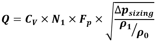
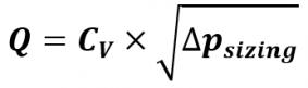
The general formula for calculating the air flow through a control valve in accordance with EN 60534-2-1 is:
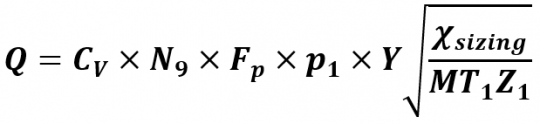
Due to the special situation on the test bench, this formula can be significantly simplified:
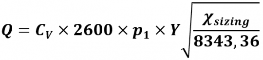
Using:
Cv The Cv (Kvs) value of the valve in m³/h.
N9 = 2600 – Numerical constant No. 9 with the value for the reference temperature 15 °C, pressure in bar and flow rate in m³/h. The standard does not provide further explanations.
FP = 1 pipe geometry factor – the test scenario only considers the valve, not any connected pipes. Therefore always “1”.
p1 Absolute pressure at the inlet of the valve. Calculated from test pressure + absolute ambient pressure >> test pressure + 1.01325 bar.
MT1Z1 = 8343.36 – The product of molar mass of air (28.97 kg/kmol) x inlet temperature (288 °K) x real gas factor (1). If you test with nitrogen, the molar mass is 28.013 kg/kmol and the value changes to 8067.74.
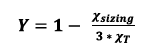
Describes the expansion factor and is calculated from the previously selected Xsizing and the valves parameter XT from step 1. Within the appendix of this document you will find a table to read Y using Xsizing and XT. The value is in any case smaller than 1. The result of this calculation is the rated capacity of the valve for the test bench scenario. The dimension of the result is m³/h.
Step 3 – Multiply the rated capacity Q by the leakage factor according to EN 60534-4
The actual EN 60534-4 standard is only applied in the last step of the leakage calculation. Table 3 – “Maximum seat leakage for each leakage class” the following factors are specified for classes I to IV-S1:
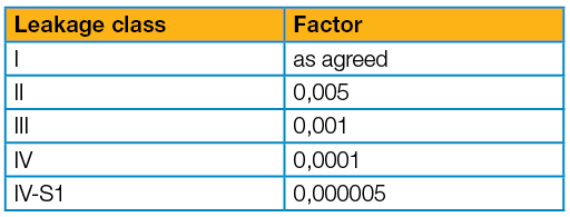
Table 2
Multiply the rated capacity Q by the factor of the leakage class to receive the permissible leakage in m³/h
The leakage is typically not given in m³/h, but in a unit appropriate to the quantity. The necessary conversion factors are to be found within the appendix.
Example calculation for air leakage:
Cv value: 160 m³/h XT: 0.7 Test pressure p1: 3.5 bar air, valve open at outlet Leakage class: IV -> factor 0.0001
Step 1 – Check for flow restriction
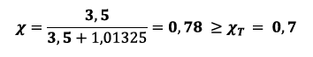
X is greater than XT >> Xsizing = XT = 0.7. Pressure restriction occurs; therefore, the XT value is used for further calculation.
Step 2 – Calculate rated capacity Q
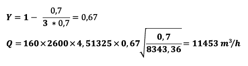
Step 3 – Multiply leakage factor
Permissible leakage = 11453 m³/h x 0.0001 = 1.145 m³/h converts to 19.1 l/min
Further conversion factors are to be found in the attachment.
Calculate water leakage in 3 steps
To calculate the permitted leakage for a test with water the following steps shall be performed in sequence:
Step 1 – Check for flow restriction
Calculate 1: Pressure difference of the test situation Δp = p1 – p2 If the valve outlet is open to environment Δp = p1 equals the test pressure.
Calculate 2: critical pressure difference for flow restriction Δpchocked. Note: Different to testing with gas the comparison parameter for pressure restriction is not given when testing with water. It must be calculated using the valves parameter FL. Δpchocked = FL² x (p1 + 1.01325 – FFpv) – universal formula Δpchocked = FL² x (p1 + 0.99) Applying the parameters for water
Using: FL Pressure recovery factor for liquids (valve parameters) p1 Test pressure at the inlet of the valve in bar relative 1.01325 – Ambient pressure – this formula uses absolute pressure FF critical pressure ratio factor in liquids (for water 0.9571) pv Absolute vapour pressure of the liquid (for water 0.0234 bar absolute)
Check: If the pressure difference Δp of the test is smaller than the pressure flow restricted difference Δpchocked, Δp is used for the calculation, otherwise use Δpchocked
Mathematically spoken:
Δp < Δpchocked -> Δpsizing = Δp
Δp > Δpchocked -> Δpsizing = Δpchocked
Δpsizing is the value used for the calculation of the flow Q in the following step.
Step 2 – Calculate rated capacity Q [m³/h] in accordance with EN 60534-2-1
The general formula for calculating the water flow through a control valve in accordance with EN 60534-2-1 is:
Due to the special situation on the test bench, this formula can be significantly simplified:
Using:
Cv The Cv value of the valve in m³/h.
N1 = 1 Numerical constant No. 1 for pressure in bar and flow rate in m³/h. The standard does not provide further explanations.
FP = 1 Pipe geometry factor – the test scenario only considers the valve, not any connected pipes. Therefore always “1”.
r1 or r0 – relative density of the fluid at temperature T1 (input) and T0 (reference condition 15 °C). for water at approx. 20 °C the result is r1/r0 = 1
The result of this calculation is the rate capacity of the valve for the test bench scenario. The dimension of the result is m³/h.
Step 3 – Multiply the rated capacity Q by the leakage factor in accordance with EN 60534-4
Step 3 does not differ for classes I to IV-S1 because the factors for water and gas testing are the same:
Table 2: Leakage factor per leakage class
Multiply the rated capacity Q by the factor of the leakage class to receive the permissible leakage in m³/h
As when testing with air when testing with water the leakage is usually converted from m³/h to a more suitable unit.
Example calculation of a permissible water leakage:
Cv value: 160 m³/h
FL: 0,9
Test pressure p1: 100 bar water, valve open at outlet
Leakage class: IV factor 0.0001
Step 1 – Check for flow restriction
Δp = 100 – 0 = 100 bar
Δpchocked = 0.9² x (100 + 0.99) = 81.8 bar
Δp is larger than Δpchocked >> Δpsizing = Δpchocked = 81.8 bar. Pressure limitation occurs, therefore the Δpchocked value is used for further calculation.
Step 2 – Calculate rated capacity Q
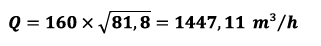
Step 3 – Leakage – multiply with factor
Permissible leakage = 1447.11 m³/h x 0.0001 = 0.1447 m³/h converts to 2.4 l/min
Further conversion factors can be found in the appendix.
Accuracy of results
The calculation of the rated capacity Q multiplies very large values (e.g. 2600) by values below 1, e.g. the formula for the value Y in the case of pressure limitation gives the value 2/3, which is a decimal value of 0.66666666666…. By multiplying the large and small values, the number of decimal places used has a visible influence on the result. When using 0.667 instead of 0.67 for Y withing the given example the result of the rated capacity Q will be 11510.23 instead of 11452.96. Consequently, a calculation using a spreadsheet program or the METRUS Leak Calculator, computing 16 decimals, will give a slightly different result than a calculation with a pocket calculator and paper, where fewer decimals are used. However, since “only” a permissible leakage is calculated, this inaccuracy can be tolerated.
Leakage calculation for classes V
Class V is much easier to calculate, as only the seat diameter or the pressure difference is required. The rated capacity is not calculated via the Cv value.
Calculation for test fluid air/gas
Important: For leakage class V, a test pressure of 3.5 bar is mandatory when testing with air. Consequently, the pressure difference is not part of the calculation formula:
Leakage [m³/h] = 10.8 x 10EXP-6 x D
Using:
10,8 x 10EXP-6 = 0,0000108
D Valve seat diameter [mm]
m³/h = 1000 x 1000 / 60 / 0.15 bubbles/min [conversion in accordance with EN 60534-4].
The formula simplifies to:
leakage [EN bubbles/min] = 1.2 x D
Calculation example: Valve with seat diameter 80 mm
Perm. leakage = 1.2 x 80 = 96 bubbles/min
At such a limit it is already recommended to work with electronic flow measurement.
Calculation for test fluid water
The single important aspect when testing class V with water is the general formula delivering already a result in [l/h]:
Leakage [l/h] = 1.8 x 10EXP-5 x Δp x D
Using:
1,8 x 10EXP-5 = 0,000018
D Valve seat diameter [mm]
Δp = Differential pressure inlet-outlet (bar rel.) = pinlet in case poutlet = Ambient pressure
l/h = 1000 / 60 ml/min [conversion].
The formula simplifies to:
leakage [ml/min] = 0.0003 x pinlet x D
Calculation example: Valve with seat diameter 80 mm
Test pressure 100 bar
Perm. leakage = 0,0003 x 100 x 80 = 2,4 ml/min
Such flow is easy to be measured with a common fuel measure.
Leakage calculation for class VI
Leakage class VI, being the highest class for a control valve, stipulates air or gas as the test fluid. There is no calculation for liquids at all. The calculation is based on the seat diameter, the test pressure and a leakage factor listed in EN 60534-4. The result is directly retrieved as a value in ml/min.
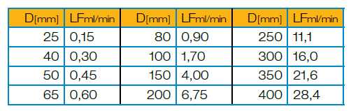
Table 3: LF – leakage factor per seat diameter for class VI
Leakage [ml/min] = 0.3 x Δp x LF [ml/min]
Using:
Δp = Differential pressure inlet-outlet (bar rel.) = pinlet when poutlet = Ambient pressure
LF [ml/min] = leakage factor according to table in ml/min
With the conversion 0.15 ml/min = 1 bubbles/min the alternative formula is
Leakage [bubbles/min] = 2 x Δp x LF [ml/min]
Calculation example:
Seat diameter 150 mm
Test pressure 6 bar
LF [ml/min] 4.00 ml/min (from table)
Leakage [ml/min] = 0.3 x 6 x 4.00 = 7.2 ml/min
or
Leakage [bubbles/min] = 2 x 6 x 4.00 = 48 bubbles/min
ANSI FCI70-2 and EN 60534-4
In the US and Canada, as well as in all industries related to the oil industry, ANSI FCI-2 is the standard for valve testing. ANSI FCI70-2 and EN 60534-4 calculate the permissible leakage in the exact same way. You can apply the calculation methods shown within this document. There are only two aspects to consider:
1) Leakage class IV-S1 does not exist in ANSI FCI70-2 2) In ANSI the Cv value is given in [liq.gal US/min] instead of [m³/h]
liq.gal US is the abbreviation for “liquid gallon”. US refers to the US American unit of measurement. The addition is important because Great Britain also uses a “liquid gallon”. However, the British gallon differs from the US gallon. To apply the formulas of EN 60534, the Cv value must be converted in the following way:
Cv [m³/h]= 0.865 x Cv [liq.gal/min].
Note: The conversion also takes into account that the Cv [m³/h] is related to 1 bar pressure differential, the Cv [liq.gal US/min] value to 1 PSI.
Appropriate measurement technology
For many decades, the bubble counter has been the instrument of choice when it comes to detecting small gas leaks. With the definition of EN 60534-4 sating: 0.15 ml/min = 1 bubble/min, leakage measurement has become possible using simple tools. A glass of water and a tube are sufficient.
Test bench software with direct data acquisition has created the need for suitable leakage measuring instruments. Influenced by the ubiquitous bubble counter, the call for an “electronic bubble counter” became loud, which most test bench manufacturers, including METRUS GmbH, meet with different product solutions.
If you realise that: 1) EN 60534 calculates permissible leakages as a proportion of the rated capacity, 2) Leakage classes V and VI first calculate a flow rate, 3) The conversion from ml/min to bubbles/min is a help to detect leakages in a simple and economic way
it becomes clear that the approach of counting physical bubbles themselves electronically is not in line with the standard. It appears smarter to detect small leakages with a sensitive flow measuring instrument and to convert them in to bubbles for comparison with traditional glass-of-water bubble counters.
There are different suppliers of flow meters and many offer a very sensitive device with a measuring range of 0 – 10 sccm (standard cubic centimetres per minute). By converting 1 sccm = 1 ml/min = 6.66667 bubbles/minute the 0 – 10 sccm sensor becomes a 0 – 67 bubbles/minute sensor. All that is necessary is to set up the display module or the connected software accordingly in order to obtain a correctly determined, electronically measured value.
Leakage calculation in accordance with EN 12266
EN 60534 is a set of rules specifically for control valves. Furthermore, there is the industrial valves standard EN 12266 that is mainly used for shut-off valves. Part 1 (EN 12266-1) of this standard contains the requirements for the leakage test.
In general, the following must be observed: 1) The test medium must have room temperature on the outlet side 2) The calculation based on the DN may also be used for diameter-equivalent inch flanges or threads 3) The calculation is based on the nominal diameter (DN) directly, following the table below
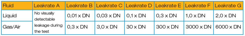
Table 4: Leakage calculation per leak rate, nominal diameter and test fluid
4) The result has the dimension mm³/s 5) Conversion to EN 60534-4 bubbles/min via: bubbles/min = 2.5 x mm³/sec
Calculation example: DN 200 fitting – test fluid air – leak rate B Permissible leakage = 0.3 x 200 = 60 mm³/sec = 24 bubbles/min.
Unlike 60534-4, the requirements of EN 12266 decrease as the letter increases. In EN 60534-4, the requirements increase as the class rises.
About the author
0 +
Articles in this section

 Valve World Expo